How can we achieve high performance camera technology that’s profitable? In this article, Envisioning the Future Clearly, Roger V Burns, Senior Director Applications Engineering, ASMPT AEi, uses a representative real camera to explore the manufacturing challenges facing the production of automotive camera.
With the growing demand for assisted driving and autonomous vehicle, visual technology aid in the vehicle visualizing the external environment, and perceptual computing capability becomes fundamental yet critical for the entire application framework. Image clarity and high resolution in detail form the basis of visual recognition and computation input data. Automotive cameras are evolving with increased resolution, field of view, and reduction in pixel size.
Camera technology has evolved to the edge of the current process capabilities to provide the performance required for Advanced Driver Assistance Systems and to advance truly Autonomous Vehicles to reality. The best utilization of the now available camera technology requires a new holistic approach. It requires an assessment of needs and the application of capabilities to extract maximum performance at a reasonable cost. The end result will promote the best performance while providing the best profitability for the production line. This is a cost-sensitive business that balances the edge of what is possible with what is cost-effective. Let us aim to maximize both aspects.
To illustrate the manufacturing challenges facing current automotive cameras, this article will use a representative real camera (8.3Mpx, 120 degree Horizontal Field Of View), allowing us to better understand the complexity of the automotive camera production process.
A. The ability to clearly define between pedestrians, vehicles and external fixtures etc. over the usable lifetime of the camera is important. The clarity of image poses a challenge for the vehicle to define the entity’s nature.

This requires optimal lens positioning to obtain the greatest usable Depth of Focus over the entire temperature range. The specific steps are as follows:
- Evaluate the constraints on optical performance over the temperature of the lens/sensor combination.
- MTF limits at various angular fields of View: Center, Outer
- Actual performance of the assembly at Low (-40 C) and High Temperature (+85 C) vs. Process Temperature (nominally around 22 C)
- Assemble the camera analyzing the points where performance will go outside of specification:
- Center Region Of Interest (ROI) – MTF >0.6
- Outer Regions of Interest (ROI) – MTF > 0.4
- Run optimizing alignment and assess marginsSet Assembly Point to allow for a shift in Lens-to-Sensor distance.
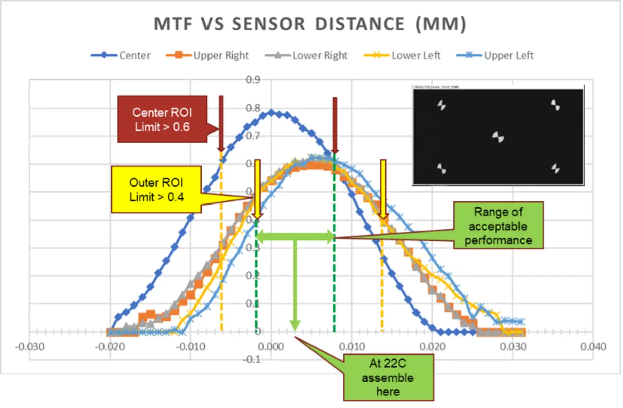
3. To complete the analysis – verify that the span of expansion/or contraction of the assembly due to the Coefficient of Thermal Expansion (CTE) and the temperature range is compatible with the margin remaining. In this case, it is ±5µm.
B. All boils down to the economics of production and hence the adaptability of the technology.
Camera Alignment in optimum time to maximize equipment throughput and economics[2]. Reduce alignment time by eliminating stop-by-motion coordination of the optical stage with image capture to provide single-pass alignment capability. This requires exact time and position coordination so that each frame captured can be identified at a specific distance from the sensor. This is easiest with Global Shutter cameras. Rolling Shutter cameras can be coordinated but it requires more care in understanding the physical location of each part of the frame. A time reduction of 50% or greater has been obtained versus the standard stop-motion Active Alignment.
C. Out-of-factory qualification and assurance of the optimum yield
Rapid camera focus evaluation after assembly can be effective for process control, predictive trend analysis to anticipate line failures and stability of the camera assembly itself over time and temperature.
The Active Alignment process obtains an optimum position of the Lens-Sensor combination for initial assembly. In order to optimize assembly it is very important to find the exact relationship of the sensor and lens in the built assembly.
Normal post-production test is done with targets at fixed distances. This one-dimensional analysis provides Pass/Fail judgment but not a full process variation analysis. While motorized targets/collimators projecting images are a powerful analysis tool to determine the actual performance of:
a. The Lens to Sensor position distance
b. Change in coplanarity of the Lens image and the Sensor plane.
c. Change in the peak optical performance for each of the ROI’s.
d. Swept Target analysis provides quantitative feedback to the Active Alignment process that eliminates guessing the root cause of degradation.
D. Resolving distortion to ensure the most accurate spatial information is attained for computation and the right action to take.
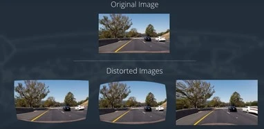
Intrinsic Parameter Calibration (IPC) in minimum time to reduce cost at full accuracy. Image linearization is a key part of camera performance for object recognition and avoidance, and image merging to present the bigger picture. Reduced time to obtain verifiable Intrinsic Parameter sets can be obtained from the Reference Camera mapping approach. This eliminates moving targets during the calibration of a calibrated reference camera of the same type as the camera under calibration. The parameters can be calculated by assessing the difference in the distortion fields of the two cameras. This approach allows the IPC calibration at up to twice the speed of the Active Alignment process.
With the rise of autonomous driving technology and growing consumer expectations for safety, camera technology has become a crucial factor in the automotive industry. Achieving high-precision and high-performance camera technology will be essential to driving the industry forward. To deliver truly world-class camera products at a cost-effective price point, with a profitable margin and superior performance, manufacturers must adopt a complete business approach that manages the entire process and technical components in real-time, down to the smallest details.
Written by Roger V Burns
Senior Director Applications Engineering, ASMPT AEi
[1] O. Kupyn, V. Budzan, M. Mykhailych, D. Mishkin and J. Matas, “DeblurGAN: Blind Motion Deblurring Using Conditional Adversarial Networks,” in 2018 IEEE/CVF Conference on Computer Vision and Pattern Recognition (CVPR), Salt Lake City, UT, USA, 2018 pp. 8183-8192.
doi: 10.1109/CVPR.2018.00854
[2] US 9,156,168 US Pat Office: Active Alignment Using Continuous Motion Sweeps and Temporal Interpolation, Andre By
